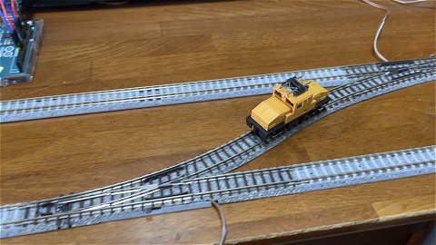
次は分岐器を一つ増やしてスイッチバックを構成してみる。と言っても、高低差を作る意味はあまり無いので、あくまで平面上でのスイッチバック実験だ。ポイントは2個を個別に制御する必要は無く、同時に同方向へ動かせば良いので、回路は前回のものと同じである。
 私の入門記録であって、入門者向け解説サイトではありません。
次は分岐器を一つ増やしてスイッチバックを構成してみる。と言っても、高低差を作る意味はあまり無いので、あくまで平面上でのスイッチバック実験だ。ポイントは2個を個別に制御する必要は無く、同時に同方向へ動かせば良いので、回路は前回のものと同じである。
自動運転は、Arduinoで実行出来る内容としては最も実用的ではないだろうか。回路は簡単で、前回のものからボリューム部分を取り除けばオーケーだ。スケッチも以下の通り、今のところ基本的に出力のみで、値を読み取るルーチンはない。前進は10番ピンに値100を出力し、後退は逆に11番ピンに出す。delayが前後進と停止の時間指定で、実験なのでこれを無限に繰り返すだけの簡単な処理である。
[ スケッチ:Pwm1]
void setup() {
  pinMode(10, OUTPUT);
  pinMode(11, OUTPUT);
}
void loop() {
  analogWrite(10, 100);
  digitalWrite(11, LOW);
  delay(2550);    // 前進
  analogWrite(10, LOW);
  digitalWrite(11, LOW);
  delay(5000);    // 5秒停止
  analogWrite(11, 100);
  digitalWrite(10, LOW);
  delay(2650);    // 後退
  analogWrite(11, LOW);
  digitalWrite(10, LOW);
  delay(5000);    // 5秒停止
}
こうなると、スケッチの信号点灯処理の繰り返し部分が気になって来る。ソフト経験のある方なら関数化したくなるのが人情と言うものだろう。
というわけで、signalSwitch() という関数を新たに設け、各信号の値をそこへ渡す形に改造したのが以下である。
[ スケッチ:IfStatementConditional31]
// These constants won't change:
const int analogPin = A0;    // pin that the sensor is attached to
const int ledPin = 13;       // pin that the LED is attached to
const int led2Pin = 12;      // pin that the LED is attached to
const int led3Pin = 11;      // pin that the LED is attached to
const int threshold = 150;   // an arbitrary threshold level that's in the range of the analog input
void setup() {
  // initialize the LED pin as an output:
  pinMode(ledPin, OUTPUT);
  pinMode(led2Pin, OUTPUT);
  pinMode(led3Pin, OUTPUT);
  // initialize serial communications:
  Serial.begin(9600);
}
void loop() {
  // read the value of the potentiometer:
  int analogValue = analogRead(analogPin);
  // if the analog value is high enough, turn on the LED:
  if (analogValue < threshold) {
    signalSwitch(1, 0, 0);  // RED
    delay(6000);
    signalSwitch(0, 0, 1);  // YEL
    delay(6000);
  } else {
    signalSwitch(0, 1, 0);  // GRN
  }
  // print the analog value:
  Serial.println(analogValue);
  delay(1);        // delay in between reads for stability
}
void signalSwitch(int x, int y, int z) {
  digitalWrite(ledPin,  x);
  digitalWrite(led2Pin, y);
  digitalWrite(led3Pin, z);
  return;
}
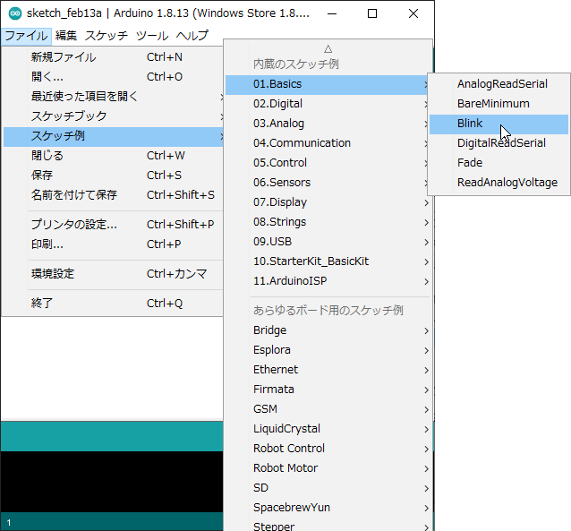
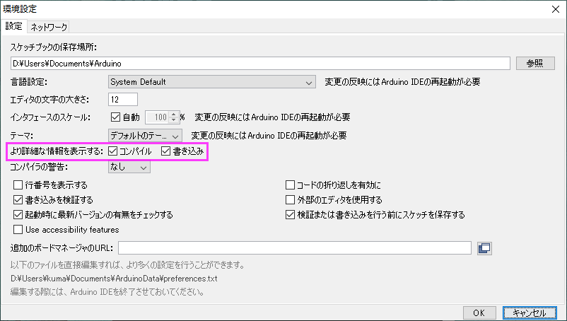
早速PCに繋いで、動作チェックを行なう。前に紹介したサンプルスケッチ「Blink」はボード上のLEDを点滅させるので、周辺回路無しでチェック出来る。その前に、メニューの「ファイル」→「環境設定」で、「より詳細な情報を表示する」にチェックを入れておくとエラーの際の原因分析が容易になると思う。
Arduino IDE を起動し、教科書に記載のサンプルプログラムをロード。使用するのは、基板上のLEDを点滅させる「Blink」という簡単なプログラム(Arduino用語ではスケッチと呼称する)である。